1986 Ford Bronco XLT |
May 30, 2012
Ford Bronco and F-Series Pickup 1986 Engine Control Module Wiring Diagram
Sponsored Links:
Here is where you can see the engine
control module wiring diagram for the 1985 Ford Bronco and the
F-Series Pickups. The Ford Bronco is an SUV that were built between
the year 1966 until 1996, the wiring diagram is intended for the
full-size Broncos (1978-1996). While the Ford F-Series is a series of
full-size pickup trucks, these trucks has a long history, they were
first made in the 1948, and continued to being produced until today.
Plymouth 6 and V8 Fury 1965 Complete Wiring Diagram
Sponsored Links:
Now we will show you the complete
wiring diagram for the 1964 Plymouth 6 and V8 Fury. The Plymouth Fury
was a premium-priced model car that were produced by Plymouth
division under the management of Chrysler corporation. This Plymouth
Fury was made between the year 1956 to 1978. It gets it's name from
the Greek mythological creature called the Furies, a type of anger.
The 1965 Fury is a full-size car with lines of Furys, they are Fury
I, Fury II, and Fury III.
1965 Plymouth Fury |
Ford V8 Thunderbird 1963 Complete Wiring Diagram
Sponsored Links:
Here is the complete wiring diagram for
the 1963 Ford V8 Thunderbird. The Thunderbird or aka T-Bird is a
personal luxury car from Ford that were first made in the 1955. The
1963 Ford Thunderbird has minor changes compared to it's predecessor,
it has a horizontal styling line, it also use a small diagonal chrome
bars in door area, for the engine part, they were using alternators
instead of generators as a new feature for the 1963 Thunderbirds.
1963 Ford Thunderbird V8 |
Ford F-100 through F-350 1970 Truck Master Wiring Diagram
Sponsored Links:
This schematic explains about the 1970
Ford F-100 through F-350 Truck master wiring diagram. The Ford's
F-Series is a full-size pickup trucks that has been produced through
six decades. The 1970 Ford F-Series was the third generation of
F-Series that includes the models F-100 (F10, F11, F14), F100 (F18,
F19)(4x4), F-250 (F25, F25), F-250 (F28, F28)(4x4), and F-350 (F35,
F36).
1970 Ford F-100 Truck |
Ford Escort Twin Cam All Models 1969 Complete Wiring Diagram
Sponsored Links:
Here is the complete wiring diagram for
the 1969 Ford Escort Twin Cam all models. But before we talk about
the wiring diagram, let's talk a bit about this car. The Escort is a
small family car from Ford. The 1969 Ford Escort was included in the
Ford Escort Mark 1 generation (1968-1974), and in the 1969 The Escort
comes in a 4-door saloon model.
1969 Ford Escort RS Mk1 |
Dodge V8 All Models 1955 Complete Wiring Diagram
Sponsored Links:
This circuit schematic is the complete
wiring diagram of the 1955 Dodge V8 all models. The 1955 Dodge V8
automobile are including; 2-door sedan Coronet, 4-door sedan Coronet,
4-door sedan Royal, 4-door sedan Custom Royal, 2-door hardtop coupe
Lancer, 2-door hardtop coupe Royal Lancer, 2-door hardtop coupe
Custom Royal Lancer, 2-door wagon Suburban, 4-door wagon Suburban,
4-door wagon Sierra, and 2-door convertible Custom Royal Lancer.
1955 Dodge Coronet |
Honda Acura Integra 1997 Charging Circuit Diagram
Sponsored Links:
The schematic will be discussed here is
the charging circuit diagram for the 1997 Honda Acura Integra. The
Acura is a luxury, performance, and near-performance car from Honda
that has been marketed for US, Canada, Hong Kong, Mexico, and China.
The 1997 Honda Acura Integra is the third generation Acura Integra.
1997 Honda Acura Integra Type R |
May 28, 2012
Eton Lightning 50 (AXL, NXL, TXL-50) ATV Lighting Impulse Wiring Diagram
Sponsored Links:
The schematic we'll show you here is
the lighting impulse wiring diagram for the Eton Lightning 50 (AXL,
NXL, TXL-50) ATV. The Lightning 50 uses two cycle air cooled engine
with 49.3 cc capacity and 5.2 hp @ 7000 rpm. The maximum rider weight
for this ATV is 68.2 kg or 190 lbs.
Eton Lightning 50 ATV |
Dodge W100 1988 Engine Control Wiring Diagram
Sponsored Links:
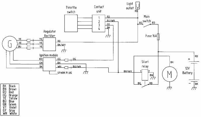
Here we can see the engine control
wiring diagram for the 1988 Dodge W100 series. This wiring diagram is
very clear and very much readable, you should find them easy enough
to understand. Here we can also see each components and their
connections, several components are such as: auto shutdown relay,
injector, alternator, throttle position sensor, purge solenoid, A/C
clutch input, overdrive lockout, ignition switch, neutral safety
switch, backup light switch, overdrive switch, etc.
Honda CB750F Motorcycle Wiring Diagram
Sponsored Links:
Here you can see the wiring diagram for
the Honda CB750F motorcycle. The CB750 series is a motorcycle from
Honda that has a long history, it was first built in the 1969, in
2003 they were also made, and then in 2007 with several models. The
Honda CB750F series were built between the year 1979-1982, this bike
was the DOHC model. This motorcycle has engine capacity of 748 cc, it
has 68 hp @ 9000 rpm, 5 speed, gearbox, constant mesh, and final
drive chain.
Honda CB750F Motorcycle |
Husaberg Desert Models 2000 Motorcycle Wiring Diagram
Sponsored Links:
Here we will show you a schematic about
the 2000 Husaberg Desert Models motorcycle wiring diagram. This
schematic is a quite simple one, we can see several components and
connections in it. We will name all of them for you, they are:
throttle switch, regulator rectifier, light outlet, spark plug, start
relay, and battery. They will also be a wiring color abbreviation
codes shown here.
Husaberg Desert Models 2000 Motorcycle
Wiring Diagram
|
Our suggestion for you is to first
study this wiring diagram comprehensively. Get the knowledge you will
need to perform your own wiring work. Be sure to perform a proper
wiring work, work safe and enjoy yourself.
Dodge Monaco 1976 Complete Electrical Wiring Diagram
Sponsored Links:
Below we shall see the complete
electrical wiring diagram for the 1976 Dodge Monaco. The Monaco was
considered as a full-size automobile from Dodge that were produced
between 1965-1978, and then built again in 1990-1992. For the 1976
Dodge Monaco, they only have few changes from their predecessor.
1976 Dodge Monaco |
Suzuki VS800 Intruder 1992 Complete Electrical Wiring Diagram (UK Version)
Sponsored Links:
You will see here the complete
electrical wiring diagram for the 1992 Suzuki VS800 Intruder
motorcycle (UK version). The VS800 Intruder is a custom or cruiser
motorcycle from Suzuki. It uses V2 four stroke engine with 50.00 hp @
6400 rpm, and it has the capacity of 805.00 cc.
1992 VS800 Intruder 450 |
Eton Thunder 90 (AXL, NXL, TXL-90) ATV Lighting Wiring Diagram
Sponsored Links:
Here we will show you the lighting
wiring diagram for the Eton Thunder 90 that includes the models AXL,
NXL, TXL-90. The Thunder 90 uses two cyce air cooled engine with 82.5
cc capacity, and has 7hp @ 7000 rpm. This all terrain vehicle
requires the maximum rider weight of 68.2 kg/190 lbs.
Eton Thunder 90 ATV |
May 24, 2012
Honda Acura Integra 1990 Starting System Wiring Diagram
Sponsored Links:
Here is the starting system wiring
diagram for the 1990 Honda Acura Integra. The Acura Integra is a
compact luxury performance coupe made by Honda during the year
1985-2006. The 1990 Honda Acura Integra was considered as the second
generation of Acura Integra (1990-1993), this generation include the
DA5-DA9, DB1-DB2.
1990 Honda Acura Integra |
Suzuki VS750 Intruder motorcycle 1988-1991 Complete Electrical Wiring Diagram (US and Canada)
Sponsored Links:
What we will show you is the complete
electrical wiring diagram for the 1988-1991 Suzuki VS750 Intruder
motorcycle (US and Canada version). The VS series has been the
cruiser motorbikes from the Suzuki. The VS750 Intruder have V-twin
with 747 cc engine capacity, water-cooled, the maximum HP of 55 HP @
7,500 rpm, and can reach the top speed of 165 km/h.
1991 Suzuki VS750 Intruder |
Suzuki VS750 Intruder motorcycle 1988-1991 Complete Electrical Wiring Diagram (UK)
Sponsored Links:
This schematic below is the complete
electrical wiring diagram for the 1988-1991 Suzuki VS750 Intruder
motorcycle (UK version). The VS series has been Suzuki's series of
cruiser motorbikes. One of the VS series is the VS750 Intruder, this
bike have 747 cc engine capacity, water-cooled, V-twin engine, and
have the maximum of 55 HP @ 7,500 rpm, and can reach the top speed of
165 km/h.
1991 Suzuki VS750 Intruder |
Suzuki VS700 Intruder motorcycle 1987 Complete Electrical Wiring Diagram (UK)
Sponsored Links:
This schematic is gonna be the 1987
Suzuki VS700 Intruder motorcycle complete electrical wiring diagram
(UK version). The VS700 Intruder is a cruiser motorcycle from Suzuki
that made their debut back in the 1986 and produced until 2005. but
the name Intruder will still be used in Europe for some Boulevard
machines.
1987 Suzuki VS700 Intruder |
Suzuki VS700 Intruder motorcycle 1986 Complete Electrical Wiring Diagram (UK)
Sponsored Links:
Here is the complete electrical wiring
diagram for the 1986 Suzuki VS700 Intruder motorcycle (UK version).
This wiring diagram is intended for the UK released Suzuki VS700
Intruder motorcycle. The VS700 Intruder is a cruiser bike from Suzuki
that were first produced in the 1986, this bike is using a
water-cooled system to remove the heat from it's components.
1986 Suzuki VS700 Intruder Motorcycle |
Suzuki VS800 Intruder motorcycle 1992 Complete Electrical Wiring Diagram (US and Canada)
Sponsored Links:
This schematic is going to be the
complete electrical wiring diagram for the 1992 Suzuki VS800 Intruder
motorcycle (this wiring diagram is for the US and Canada version).
The Suzuki VS800 Intruder is a custom or cruiser motorcycle that uses
V2 four-stroke engine. The top speed reaches 154.0 km/h (95.7 mph)
with it's 50.00 HP (35.5 KW) at 6400 RPM.
1992 Suzuki VS800 Intruder |
May 23, 2012
Suzuki GSX-250F Across motorcycle 1991 Electrical Wiring Diagram
Sponsored Links:
Here we will show you the electrical
wiring diagram for the 1991 Suzuki GSX-250F Across motorcycle. This
GSX-250F Across is a motorcycle that use a small 250 cc engine, and
considered as a sport touring motorcycle. This bike has its own good
sides and bad sides. This bike were criticized for their small fuel
tank capacity of 12L/2.6 imp gal; 3.2 US gal. But they are also
considered as a powerful motorcycle for its engine size.
1991 Suzuki GSX 250F. Across |
Suzuki SV650 motorcycle 1999-2002 Minimal Race Wiring Diagram
Sponsored Links:
We will show you the image of the
minimal race wiring diagram for the 1999-2002 Suzuki SV650
motorcycle. The SV650 is a motorcycle from Suzuki that are classed as
a street motorcycle that's using a mid-sized V-twin engine and medium
performance parts. The 1999-2002 Sv650 was included as the first
generation of this motorcycle, they were made as a naked bike, a
motorcycle that is minimally faired.
Suzuki SV650 Motorcycle |
May 22, 2012
Suzuki GSX-R600 SRAD motorcycle 1998 Complete Electrical Wiring Diagram
Sponsored Links:
This is going to be the complete
electrical wiring diagram for the 1998 Suzuki GSX-R600 SRAD
motorcycle. The GSX-R600 is a supersport from the line of Suzuki's
GSX-R series motorcycle with 600 cc capacity. The 1998 Suzuki
GSX-R600 have used the Suzuki Ram Air Direct (SRAD).
1998 Suzuki GSXR-600 SRAD |
Suzuki GN400 motorcycle Complete Electrical Wiring Diagram
Sponsored Links:
This schematic will be the complete
electrical wiring diagram for the Suzuki GN400 motorcycle. The GN
includes as a standard motorcycle from Suzuki that were first made in
early 1980s. All GN series are using air-cooled SOHC single-cylinder
engines with chain drive. Based on the SP400 Enduro motorcycle, the
GN400 doesn't use an electric starter, but it is using tachometer and
a manual decompression system.
1980 Suzuki GN400 |
May 20, 2012
Suzuki DR650 motorcycle Complete Electrical Wiring Diagram
Sponsored Links:
This schematic right here is the
complete electrical wiring diagram for the Suzuki DR650 motorcycle.
The Dr650 is a motorcycle from Suzuki with a long history since 1990.
The DR model is a dual-sport motorcycle that used counterbalanced,
single cylinder, air/oil-cooled engine that produce 46 HP.
1996 Suzuki DR650 |
Chrysler LeBaron 1990 Horn System Wiring Diagram
Sponsored Links:
Here is going to be the horn system
wiring diagram for the 1990 Chrysler LeBaron. The Chrysler LeBaron is
also known as the Chrysler Imperial LeBaron, it was a classic luxury
car from Chrysler. The nameplate LeBaron has been used by Chrysler
for decades. In 1990 the LeBarin has a refreshed interior with new
dashboard, door panels. Gauge cluster, and new center console design.
1990 Chrysler Le Baron 2.2 GTC Cabrio |
Buick Roadmaster Series 50 and 70 1952 Chassis Wiring Circuit Diagram
Sponsored Links:
Here we're gonna see the 1952 Buick
Roadmaster series 50 and 70 chassis wiring circuit diagram. The
Roadmaster is being produced by Buick during the year 1936 until
1958, but in 1991 until 1996, the name Roadmaster is being used as a
Buick's full size rear-wheel drive models. The 1952 Roadmaster has
the option of power steering with them, and thanks to the new
four-barrel carburetor, the horse power is increased to 170 hp.
1952 Buick Roadmaster Series 70 |
May 17, 2012
Buick Riviera 1964 Complete Electrical Wiring Diagram
Sponsored Links:
This schematic right here will be the
complete electrical wiring diagram for the 1964 Buick Riviera. The
Riviera was being produced by Buick since the year 1963 until 1999.
The 1964 Buick Riviera was the first Riviera that uses the emblem R
and then it's being used for the rest of the Riviera for the next 36
years.
1964 Buick Riviera |
Buick Roadmaster Series 40 1952 Chassis Wiring Circuit Diagram
Sponsored Links:
You will see here the 1952 Buick
Roadmaster series 40 chassis wiring circuit diagram. The Roadmaster
is a car from Buick that has a long history since it's appearance in
the 1936. The 1952 Buick Roadmaster has the option of power steering,
and with the new four-barrel carburetor the horsepower increased to
170 hp.
1952 Buick Roadmaster Series 40 |
May 16, 2012
Buick Roadmaster 1952 Dome Lamp Wiring Diagram
Sponsored Links:
Here we will show you the dome lamp
wiring diagram for the 1952 Buick Roadmaster. The Roadmaster is the
car that were the top of the line model of Buick during the year
1946-1957. The 1952 Roadmaster has the option of power steering, and
the horsepower is increased to 170 because of the new 4-barrel
carburetor.
1952 Buick Roadmaster Convertible |
May 15, 2012
Buick Riviera 1965 Console Circuit Diagram
Sponsored Links:
The next schematic shown to you here is
the console circuit diagram for the 1965 Buick Riviera. The Riviera
is a full-size sedan by Buick that were produced from 1063-1999. The
1965 Riviera is included in the first generation of Riviera, they
were convinced as the styling landmark, and become a collector's item
today.
1965 Buick Riviera |
Buick Roadmaster 1938 Electrical Wiring Diagram
Sponsored Links:
You will see below the electrical
wiring diagram for the 1938 Buick Roadmaster. The Roadmaster was
built between the year 1036 until 1958. And in 1991-1996 Buick also
used this Roadmaster name again for their full-size rear-wheel drive
car. The 1938 Buick Roadmaster has the engine of 320 cu in (5.2L)
Fireball I8.
1938 Buick Roadmaster |
Buick LeSabre, Invicta, Wildcat, and Electra 1963 Complete Electrical Wiring Diagram
Sponsored Links:
We'll be showing you the complete
electrical wiring diagram for the 1963 Buick LeSabre, Invicta,
Wildcat, and Electra. But here we're only going to show you a bit of
information on the LeSabre only. The Buick LeSabre is a full-size car
from Buick that has been built since 1059 to 2005. The 1963 Buick
LeSabre was the second generation of Buick, during this year the
LeSabre has some major facelift with even more boxier body contours.
1963 Buick LeSabre |
Harley Davidson FL-FLH 1973-74 Motorcycle Electrical Wiring Diagram
Sponsored Links:
You will see here the electrical wiring
diagram for the 1973-74 Harley Davidson FL-FLH motorcycle. One of the
most famous FL series motorcycle from Harley Davidson is the FL model
Electra Glide. This motorcycle has a second disc brake added to them.
The hand shift models are no longer exist, now riders must shift
gears with their boot, and since 1973 this motorcycle also has no
kick-start pedal, it uses electric starting system.
1973 Harley Davidson FL 1200 Electra Glide |
Aston Martin DB3S Electrical Wiring Diagram
Sponsored Links:
What we'll be seeing here is the
electrical wiring diagram for the Aston Martin DB3S. The DB3S is a
sport racing car built by the Aston Martin, the DB3S is the
replacement for the Aston Martin DB3, that are considered as heavy
and uncompetitive sport racing car. This DB3S was first introduced
back in the 1953, and in 1956 it was replaced by the DBR1.
Aston Martin DB3S |
Kawasaki KLR650 A9 1995 Motorcycle Electrical Wiring Diagram
Sponsored Links:
Here we'll see the electrical wiring
diagram for the 1995 Kawasaki KLR650 A9. The KLR650 series from
Kawasaki is a dual-sport motorcycle from Kawasaki that has a long
history since it's first appearance back in 1987, and has almost no
changes until 2005. Some specs for the 1995 KL650 A9 are:
5-speed-return shift, 4-stroke, 1-cylinder, DOHC, and liquid-cooled
engine.
1995 Kawasaki KLR650 A9 |
Harley Davidson XL-XLCH 1973-1974 Motorcycle Electrical Wiring Diagram
Sponsored Links:
This going to be the motorcycle wiring
diagram for the 1973-74 Harley Davidson XL-XLCH series. One of the
XLCH series is the Harley Davidson XLCH 1000 Sportster that are
categorized as classic motorcycle, this bike has the power of 57.00
HP (41.6 KW) @ 6000 RPM and can reach the top speed of 185.0 km/h
(115.0 mph).
1974 Harley Davidson Ironhead XLCH Sportster |
Alfa Romeo Giulietta Spider Veloce 10107 Wash System Wiring Diagram
Sponsored Links:
Here you will see this wash system
wiring diagram for the Alfa Romeo Giulietta Spider Veloce model
10107. The Alfa Romeo was a subcompact car by Alfa Romeo, an Italian
car producer that produced this car back in 1954 to 1965. the
Giulietta Spider is an open two-seat that has convertible model.
Alfa Romeo Giulietta Spider Veloce 10107 |
Buick Riviera 1964 Electrical Wiring Diagram
Sponsored Links:
Here you'll see the electrical wiring
diagram for the 1964 Buick Riviera. The Buick Riviera has several
changes compared to its predecessor the '63 Riviera. Changes are like
a new stylized “R” emblem for Riviera, and the best change is in
the reconfiguration of heating and air conditioning control.
1964 Buick Riviera |
May 14, 2012
Chrysler Concorde 1993 Radio Circuit System Wiring Diagram
Sponsored Links:
Here will we see the radio circuit
system of the 1993 Chrysler Concorde. The Concorde was a sedan from
Chrysler that were produced between 1993 to 2004. this car is a large
four-door, front wheel drive, full-size sedan by Chrysler. The 1993
Chrysler Concorde uses 3.3L EGA V6 and 3.5L EGJ V6 engines.
1993 Chrysler Concorde |
Cadillac De Ville 1984 Instrument Panel and Under Dash Wiring Diagram
Sponsored Links:
The schematic here is the instrument
panel and under dash wiring diagram for the 1984 Cadillac De Ville.
The Cadillac De Ville has a very long history through out the years,
it's early history was back in the 1949 and they are still producing
this car for so long until a few years back in the 2006. This shows
that this car has their own fans.
1984 Cadillac Deville |
Subscribe to:
Posts (Atom)