 |
| 1964 Ford F-250 Pickup Truck. |
June 29, 2012
Ford F-100 Through F-750 Trucks 1964 Master Wiring Diagram
Sponsored Links:
This is going to be the Master Wiring Diagram for the 1964 Ford Pickup Truck Series of F-100 through F-750. These pickup trucks has a long history throughout the years, and Ford is still producing them today. The F-Series trucks are first made in the 1948, and they has been around for 12 generations until present day.
June 22, 2012
Ford F-100 Through F-750 Trucks 1964 Exterior Lighting, Turn Signals, and Horn Wiring Diagram
Sponsored Links:
Here we'll be showing you the exterior lighting, turn signals, and horn wiring diagram for the 1964 Ford F-Series F-100 through F-750. The F-Series Trucks from Ford is a truck with long history behind them. They were first made in the 1948, and until today they are still being produced. The 1964 Ford F-Series was the fourth generation of Ford F-Series Trucks that were made between the year 1961-1966.
 |
| 1964 Ford F-250 Fire Truck |
Ford F-100 Through F-750 Trucks 1964 Instrument Panel Wiring Diagram
Sponsored Links:
This is where you can find the instrument panel wiring diagram for the 1964 Ford F-100 through F-750 F-Series Trucks. The F-Series is a full-size pickup truck series that has been around since 1948 until today. The F-Series was the best-selling vehicle in the US for 28 consecutive years according to the Wikipedia.
 |
| 1964 Ford F750 Fire Truck |
June 21, 2012
Ford B-, F-, T-Series Trucks 1964 Transmatic Transmission Wiring Diagram
Sponsored Links:
Today we will be showing you the 1964 Ford B-, F-, and T-Series transmatic transmission wiring diagram. But before we see the wiring diagram we will tell you a little story about the 1964 Ford F-Series. The F-Series is a full-size pickup trucks that manufactured first in 1948 until present day. The 1964 F-Series were included as the fourth generation of Ford F-Series, they also including models of F-100 (F10, F11, F14), F-100 (F18, F19)(4x4), F-250 (F25), F-250 (F26)(4x4), and F-350 (F35).
 |
| 1964 Ford F-Series |
Ford B-, F-, T-Series Trucks 1964 Interior Lighting, Windshield Wiper, and Gauge Wiring Diagram
Sponsored Links:
Now we are going to see the 1964 Ford B-, F-, and T-Series Trucks interior lighting, windshield wiper, and gauge wiring diagram. But before we go there, we will tell you a little story about the Ford T-Series. The only 1964 Ford T-Series reference we can find is the Ford Transit. This was the first generation of Transit also known as the Mark 1. The Transit was manufactured in Germany, since 1961 The Mark 1 was named the Ford Taunus Transit, they ended the production in the 1965.
| 1964 Ford Taunus Transit |
Ford B-, F-, T-Series Trucks 1964 Ignition Wiring Diagram
Sponsored Links:
Herein we will show to you the ignition wiring diagram for the 1964 Ford B-, F-, and T-Series Trucks. We will only discuss a bit about the 1964 Ford B-Series here. The B-Series during the year 1961 until 1966 had a horizontal grille and fenders that designed for a larger wheels to fit in. They also used a single light that were integrated with the grille.
 |
| 1961 - 1966 Ford B-Series |
Ford B-, F-, T-Series Trucks 1964 Accessories Wiring Diagram
Sponsored Links:
What we will show you here is the accessories wiring diagram for the 1964 Ford B-Series, F-Series, and T-Series Trucks. Before we get to the wiring schematic part, let us tell you what trucks are included into those series above. First the 1964 B-Series, the trucks included were the Ford I6, and Ford FT V8. The truck that represent the F-Series truck was the Ford Ranger. While the T-Series truck was the Ford Transit.
 |
| 1964 Ford F-Series Pickup |
June 19, 2012
Honda ST70 Motorcycle Wiring Diagram
Sponsored Links:
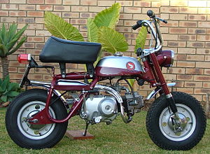
Herein we can see the wiring diagram for the Honda ST70 motorcycle. The Honda ST Series has many different names depending on which country they were released, for instance, the ST-Series were known as the Honda Dax in the Europe, in the US and Canada they were known as the Trail 70, and back in Japan, they were known as the Honda Dachshund. This minibikes used OHC 4-stroke 49-72 cc capacity engine. It has 3-speed transmission with top speed up to 70-75 km/h.
 |
| Honda Dax ST70 Motorcycle |
Honda SL70 Motorcycle Wiring Diagram
Sponsored Links:
Now we will be seeing this wiring diagram for the Honda SL70 motorcycle. The SL70 from Honda was a small motorcycle that uses a cradle frame and a 4-speed transmission. It made it's debut back in the 1971 and ended their production in 1976. The motorcycle was a 4-stroke with an air cooled single cylinder engine and single overhead cam.
 |
| 1971 Honda SL70 K0 Motorcycle |
Yamaha YZF-R1 Motorcycle Wiring Diagram
Sponsored Links:
What we will be sharing here is the Yamaha YZF-R1 motorcycle wiring diagram. The Yamaha YZF-R1 itself is an open class sport bike or a superbike that has been around since 1998. This motorcycle has 6-speed transmission, it has 4.7 gallons of fuel capacity, their brakes is using the hydraulic discs. The engine capacity is 998 cc.
 |
| Yamaha YZF-R1 Motorcycle |
Honda XL175 and XL175K1 Motorcycle Wiring Diagram
Sponsored Links:
Today we will be seeing the complete wiring diagram for the Honda XL175 and XL175K1 motorcycle. The Honda XL175 itself was a dual-sport motorcycle from Honda, the dual-sport means that this motorcycle is meant for two road conditions, on and off-road. First manufactured in the 1973 it's production continued until 1978. This motorcycle uses 5-speed transmission with only a kick-starter to get it started. It has the engine capacity of 173 cc single cylinder OHC 4-stroke engine.
 |
| Honda XL175 Motorcycle |
Honda CBR1000RR Motorcycle Wiring Diagram
Sponsored Links:
Hello there, how are you doing? We are here to show you the wiring diagram for the Honda CBR1000RR motorcycle. This motorcycle is also known as the Honda Fireblade. The bike has the engine capacity of 999 cc. The Fireblade was first introduced in the 2004, they are the replacement motorcycle for the earlier CBR954RR.
 |
| Honda CBR1000RR Motorcycle |
June 15, 2012
Ford Falcon 1964 Lighting System and Horns Wiring Diagram
Sponsored Links:
Hello there, today we will be showing you the lighting system and horns wiring diagram for the 1964 Ford Falcon. This Ford Falcon was manufactured between 1960 until 1970. The 1964 Ford Falcon has more modern look with a more squared design. They also added a more louder exhaust and more stiffer suspension.
 |
| 1964 Ford Falcon Sprint |
June 14, 2012
Mercury Comet 1964 Instrument Wiring Diagram
Sponsored Links:
This is going to be the instrument wiring diagram for the 1964 Mercury Comet. The Mercury Comet was an intermediate car or compact car made by one of Ford Motor Company's division, the Mercury. The 1964 Mercury Comet was included in the first generation of Comet, this cars uses 144 cu in (2.4L) I6, 170 cu in (2.8L) I6, and 260 cu in (4.3L) V8 engines.
 |
| 1964 Mercury Comet Caliente |
June 13, 2012
Chevrolet V8 Trucks 1981-1987 Electrical Wiring Diagram
Sponsored Links:
Herein we can see the 1981-1987 Chevrolet V8 Trucks electrical wiring diagram. The third generation of Chevrolet Trucks that can use this wiring diagram are the ones that uses 305 cu in (5.0L), 350 cu in (5.7L), 400 cu in (6.6L), 454 cu in (7.4L), 350 cu in (5.7L), and 379 cu in (6.2) V8 engines.
 |
| 1981 Chevrolet Silverado Truck |
Honda CX500 C Motorcycle 1979-1981 and CX500 D 1979 Complete Wiring Diagram
Sponsored Links:
Hi there, today we will be showing you the complete wiring diagram of the 1979-1981 Honda CX500-C and the 1979 Honda CX500-D. And this wiring diagram will also covers the UK's CX500-C, and CX500-B. The CX Series from Honda was a motorcycle that have uncommon features in them if we compare them with other motorcycle in that era. For instance, this motorcycle used an electric starter, liquid cooling, modular wheels, low-maintenance shaft drive, and also a dual CV-type carburetors.
 |
| 1979 honda CX500 Custom |
Honda CX500 Motorcycle 1978-1979 Complete Wiring Diagram
Sponsored Links:
Here is going to be the complete wiring diagram for the 1978-1978 Honda CX500 motorcycle. The CX Series from Honda were built in the late 1970s. These bikes have features that are not yet common for other motorcycles at the time, they have electric-only starter, liquid cooling, low-maintenance shaft drive, dual CV-type carburetors, etc. The Honda CX500 had a large fuel tank capacity, round brake fluid reservoir, and a plastic small fairing, also a stepped seat.
 |
| 1978 Honda CX500 Motorcycle |
Honda Z50JP Motorcycle 12V Wiring Diagram
Sponsored Links:
Today we will show you the 12V wiring diagram for the Honda Z50JP motorcycle. The Z-Series are the mini bikes series from Honda, and one of them is the Honda Z50J. The Z50J was first made in the 1973 was marketed in Europe and Japan, and in the US they were known as the Z50A.
 |
| Honda Z50A Mini Bike |
Ford Mustang GT 5.0 L 1994-1995 EEC Pinout Wiring Diagram
Sponsored Links:
We will show you in this page the EEC pinout wiring diagram for the 1994-1995 Ford Mustang GT 5.0 L. The Ford Mustang was a sport car-like coupe that have long hoods and short rear decks. The Ford Mustang GT was a higher performance and better handling car compared to the predecessor the 1993 Ford Mustang. This Mustang GT uses 302 CID Windsor pushrod small block engine, this engine burst out 215 HP @ 4200 RPM.
 |
| 1994 Ford Mustang GT 5.0 L |
June 12, 2012
Honda XL100 Motorcycle Complete Wiring Diagram
Sponsored Links:
In this page we will be showing you the complete wiring diagram of the Honda XL100 motorcycle. The XL100 was a motorcycle from Honda that were manufactured between the year 1974 to 1978. The engine was using the OHC single cylinder with 99cc capacity and 5-speed transmission.
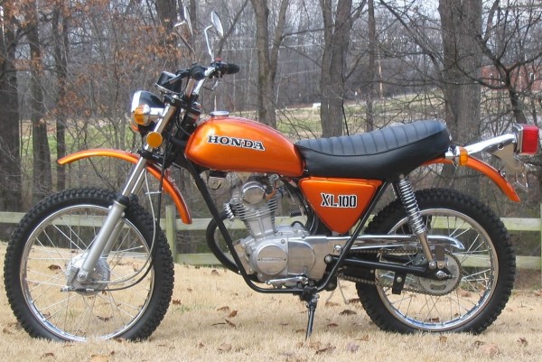 |
| 1974 Honda XL100 Motorcycle |
Honda CL100 Motorcycle 1970-1973 Complete Wiring Diagram
Sponsored Links:
Today we are going to show you this complete wiring diagram for the 1970-1973 Honda CL100. This Honda CL100 was a 4-stroke single cylinder overhead cam motorcycle that were manufactured in the US between 1970 until 1973. This CL100 motorcycle can also be called as dual sport bike or the Scrambler. According to the manufacturer, Honda, this motorcycle has 99 cc capacity 4-stroke engine, 5-speed transmission, high mount chrome exhaust with leg heat-shield, electrical system with full 6v, and speedometer with high beam indicator, neutral light, and odometer.
 |
| 1972 Honda CL100 Motorcycle |
Ford All Models 1937 Wiring Diagram
Sponsored Links:
Hello friend, here you can see this wiring diagram for the 1937 Ford All Models. One major changes for the 1937 Ford cars, the 136 CID (2.2L) V8 engine was introduced as an addition of the older and famous 221 CID (3.6L) flathead V8 engine. The 1937 Ford has the overall looks that are more rounded and with fine horizontal bars in the convex front and hood-side grilles.
 |
| 1937 Ford Deluxe Convertible Sedan |
Ford Thunderbird 1965 Windows Control Wiring Diagram
Sponsored Links:
Here we are going to show to you the 1965 Ford Thunderbird windows control wiring diagram. The personal luxury car Ford Thunderbird was also known as the T-Bird. The 1965 Thunderbird was the fourth generation of the whole eleven generations of Thunderbird. The 1965 Thunderbird has the sequential turn signals, horizontal tail lights, and the standard front disc brakes were added.
 |
| 1965 Ford Thunderbird |
Ford and Mercury 1964 Windows Control Wiring Diagram
Sponsored Links:
Hi there, you are about to see the window control wiring diagram for the 1964 Ford and Mercury. The Mercury was an automobile division by the Ford Motor Company. One of the famous Mercury car was the Comet. Mercury Comet was originally shared the same base of the Ford Falcon and then later the Ford Maverick, but the Comets has slightly longer wheelbase and better interior trim.
 |
| 1964 Mercury Comet Caliente Hardtop |
Ford Thunderbird 1963-1964 Windows Control Wiring Diagram
Sponsored Links:
Here will be discussed the windows control wiring diagram for the 1963-1964 Ford Thunderbird. The Thunderbird is known also as the T-Bird was a personal luxury car from Ford that has been around for a very long time, approximately for eleven model generations. They were first manufactured in the 1955 and the last T-Bird was made in the 2005. The 1963 Thunderbird was a preparation for a new model and design of a 1964 Thunderbird, that's why there are several changes were made. The Thunderbird has a horizontal styling line from the front bumper to the rear fender through the door. They also have a small diagonal chrome bars that runs through the door to the back. For the electrical system, alternators were a new feature in a 1963 Thunderbirds.
 |
| 1963 Ford Thunderbird |
June 11, 2012
Ford Thunderbird 1961-1962 Windows Control Wiring Diagram
Sponsored Links:
This is where you
can see the windows control wiring diagram for the 1961-1962 Ford
Thunderbird. The Thunderbird or T-Bird is considered as a personal
luxury car created by Ford, and the 1961-1963 Thunderbird was the
third generation. This generation of Thunderbird has that distinctive
look, it has the bullet-like appearance. They also has the new engine
of 390 cu in (6.4L) FE V8 which produced 300 HP.
 |
| 1961 Ford Thunderbird |
Ford Thunderbird 1959-1960 Windows Control Wiring Diagram
Sponsored Links:
Here is the
windows control wiring diagram for the 1959-1960 Ford Thunderbird. The
Thunderbird or also known as the T-Bird was a personal luxury car
from Ford that has been around for eleven different generations. This
wiring diagram is intended for the second generation of Thunderbird
which built between 1958-1960.
 |
| 1959 Ford Thunderbird Convertible |
Ford Mustang 1968 Tachometer Wiring Diagram
Sponsored Links:
This will be the
tachometer wiring diagram for the 1968 Ford Mustang. The Ford Mustang
is an American sport car-like that were meant as a pony car in their
first appearance back in the 1964. Pony car means that it was first
made as an affordable in price, compact in size, have a high styling
as a sporty performance-oriented looks.
 |
| 1968 Ford Mustang Fastback GT |
Ford Mustang 1988-1990 2.3L EEC Wiring Diagram
Sponsored Links:
We will show you
here the EEC wiring diagram for the 1988 till 1990 Ford Mustang 2.3L.
The Ford Mustang was a sport car that made their debut back in the
1964 in the US. The wiring diagram here is intended for the third
generation of the Ford Mustang that were built between the year
1979-1993.
 |
| 1990 Ford Mustang LX 2.3L |
June 07, 2012
Ford Escort - Orion 1990 Starting, Charging, and General Engine Wiring Diagram (Europe)
Sponsored Links:
Here we'll be
talking to you about this 1990 Ford Escort starting, charging, and
general engine wiring diagram (Europe). The Ford Escort is a small
family car that were produced between 1968-2000 in Europe.
.jpg) |
| 1990 Ford Escort (Europe) |
Mini Clubman Saloon and Estate 1976 Electrical Wiring Diagram
Sponsored Links:
The schematic we
will be seeing here is the electrical wiring diagram for the 1976
Mini Clubman Saloon and Estate. The Mini is a small economy city car
that are very famous in Britain and worldwide.
 |
| 1976 Mini Clubman 1100 Saloon |
Honda CB650SC Nighthawk Motorcycle Wiring Diagram
Sponsored Links:
Now we're gonna
show you the wiring diagram for the Honda CB650SC Nighthawk
motorcycle. The Honda CB650SC was also known as the Nighthawk 650, a
standard motorcycle from Honda that were being produced back in 1982
until 1985. This motorcycle is using 656cc air/oil-cooled inline
four-cylinder engine with 72HP @ 10.000 rpm, 6-speed transmission,
shaft drive.
 |
| 1982 Honda CB 650SC Nighthawk |
Honda CB200 Motorcycle Wiring Diagram
Sponsored Links:
Herein we can see
the wiring diagram for all Honda CB200 motorcycle. The Honda CB200
has many names depending on where they were marketed, they were known
for models CB200K, CB200T, CB200B, and CB200A. This bike was a sport
motorcycle that were well built and solid, simple with a street
motorcycle look. It uses both electric and kick starter, dual
carburetor, and five speed gearbox.
 |
| 1975 Honda CB200 |
Honda C72 and C77 Motorcycle Wiring Diagram
Sponsored Links:
This page is where
you can find the Honda C72 and C77 motorcycle wiring diagram. The
Honda C72 and C77 have different engine capacity, the C72 has 250cc,
while the C77 has 305cc, but they are both, along with the Honda C71
Dream and C76 were the first larger-capacity motorbikes from Honda
that were being mass-exported. All of motorcycles above uses pressed
steel frame and alloy overhead cam twin cylinder engines, 12v
electrical battery, indicators, two-seaters, and also electric
starter.
 |
| 1965 Honda C77 305cc Motorcycle |
Ford 6 and V8 Mustang 1965 Complete Wiring Diagram
Sponsored Links:
Here we can see
the complete wiring diagram for the 1965 Ford 6 and V8 Mustang. The
Ford Mustang is a sports car-like coupe that have long hoods and
short rear decks. The 1965 Mustang was included in the first generation
of Mustang (1964 ½-1973).
 |
| 1965 Ford Mustang Coupe V8 |
Ford Mustang 5.0L 1990 EEC-IV Engine Performance Wiring Diagram
Sponsored Links:
We are here to
discuss this EEC-IV engine performance wiring diagram for the 1990
Ford Mustang 5.0L. There are two engines used in the 1990 Ford
Mustang, the 88HP 2.3L 4-cylinder and the husky 225HP 5.0L V8 used in
the Mustang GT and LX 5.0. The V8 5.0L engine is the engine that made
the Mustang famous as a muscle-car. This car is a car with a clean
low-mileage, a solid-running car that need little or no repair.
 |
| 1990 Ford Mustang 5.0L Convertible |
June 06, 2012
Honda SL350 Motorcycle Complete Wiring Diagram
Sponsored Links:
This schematic is
going to be explaining about the complete wiring diagram for the
Honda SL350 motorcycle. Honda Sl350 have several different types
according to the production year. In the 1969 until 1970, they were
the Honda SL350 KO, between 1970 until 1971 they are the Honda SL350
K1 and plain Honda SL350, and then in the 1972 to 1973 they were the
Honda SL350 K2.
 |
| 1972 Honda SL350 K2 |
Honda CB160 and CL160 Motorcycle Complete Wiring Diagram
Sponsored Links:
Now we will show
you a schematic, this is the complete wiring diagram for the Honda
CB160 and CL160 motorcycle. The Honda CB160 is a Super Sport
motorcycle while the CL160 is a Scrambler, but they share the same
wiring system schematic. Both of these motorcycle have the capacity
of 160cc.
 |
| 1966 Honda CL160 |
Volvo 123 GT Complete Wiring Diagram
Sponsored Links:
What we will see
here is the complete wiring diagram for the Volvo 123 GT. The Volvo
123 GT is originally the Volvo Amazon, a mid-size car that were
firstly introduced in the 1959. Then in the 1967 the Volvo 123 GT
arrived, this car was using a 130 high compression 4-cylinder B18B
engine that generates 130, fully reclining seats, M41 gearbox,
driving lights, front fog lights, tachometer, fender mounted mirrors,
etc.
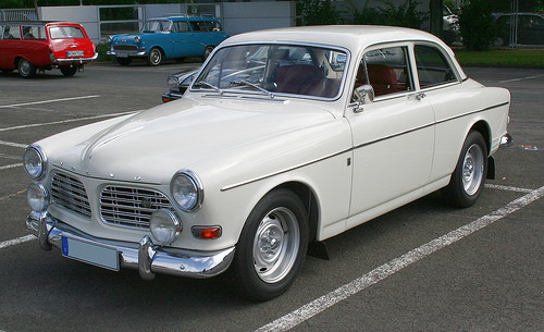 |
| Volvo Amazon 123 GT |
Honda CT90 Motorcycle Wiring Diagram
Sponsored Links:
Herein we can find
the wiring diagram for the Honda CT90 motorcycle. The CT90 was a
small step-through bike that were built by Honda between 1966-1979.
There were two models made, the Trail or the X. This bike were well
accepted all around the world, in fact, today this bike is highly
collectable. This motorcycle was an 89cc 4-stroke air-cooled single,
4-speed transmission, and an automatic clutch.
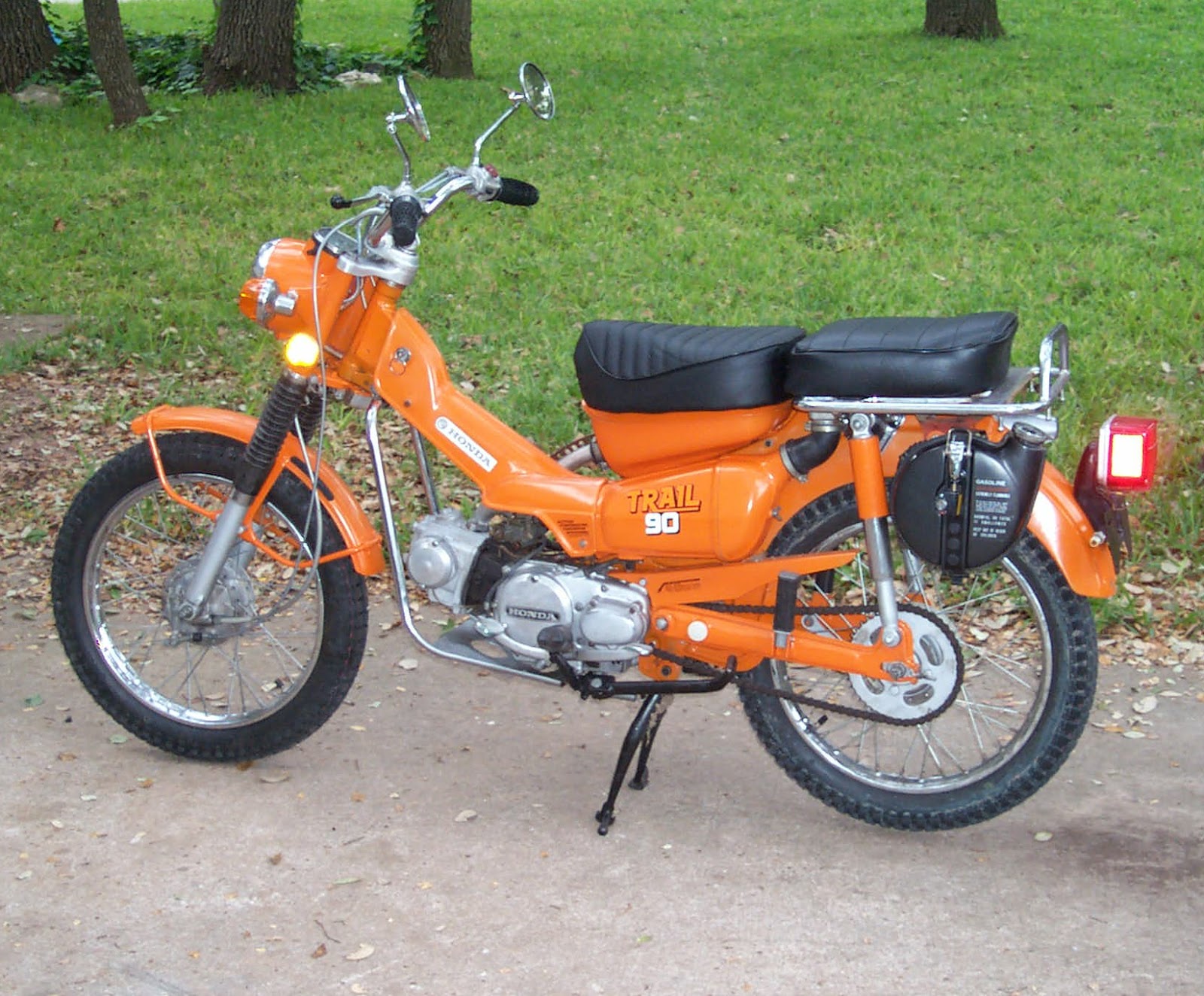 |
| 1975 Honda CT90 |
Dodge 50 Series Complete Wiring Diagram
Sponsored Links:
This is where you
can find the complete wiring diagram for the Dodge 50 Series. Dodge
50 Series or also known as the Renault 50 Series were a light
commercial vehicle that were built in the UK and then later on
continued by Renault (now Volvo) since 1979 until 1993.
 |
| Renault-Dodge 50 Series |
Ford 6 Cylinder All Models 1957 Wiring Diagram
Sponsored Links:
Herein we will see
the wiring diagram for the 1957 Ford 6 cylinder all models. The 1957
Ford 6 cylinder are including car models like Custom, Custom 300,
Fairlane, Fairlane 500, Ranchero, Thunderbird, and Thunderbird
Special. For the 1957, the Ford cars were made larger, until 1959.
 |
| 1957 Ford Thunderbird Convertible |
Honda CR-V 1997 System Warning Wiring Diagram
Sponsored Links:
This schematic
will be the system warning wiring diagram for the 1997 Honda CR-V.
The CR-V is a compact SUV or in North America, a crossover. The 1997
Honda CR-V was included in the first generation of CR-V that produced
between 1995-2001. This generation of CR-V has the engine options of
2.0L 130HP and the 2.0L 150HP, and the transmission options of
5-speed manual and 4-speed automatic.
 |
| 1997 Honda CR-V |
Ford F-150 1997 Instrument Cluster Wiring Diagram
Sponsored Links:
This is going to
be the instrument cluster wiring diagram for the 1997 Ford F-150.The
F-Series from Ford is a full-size pickup trucks that has been around
for more than 6 decades. And guess which series is the most popular
among the F-Series, yes it's the F-150, they are simply the
best-selling truck for more over than 34 years now. The 1997 F-150
have changes in the design, they are more aerodynamics with a rounded
style, better fuel economy, and a larger interior.
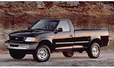 |
| 1997 Ford F-150 |
Ford F-250 1986 Engine Control Module Wiring Diagram
Sponsored Links:
Herein we will be
seeing the engine control module wiring diagram for the 1986 Ford
F-250. The F-250 is included in the F-Series from Ford, a full-size
pickup trucks that have been around for sixty years.
 |
| 1985 Ford F-250 |
Audi S4 20 Valve Cylinder 1992 Wiring Diagram
Sponsored Links:
This schematic
right here is the wiring diagram for the 1992 Audi S4 20 valve
cylinder. This Audi S4 a high performance version of the compact
executive vehicle from Audi also, the A4. The original S4 was
produced between 1991-1994. The 1992 Audi S4 is also known as the
Audi C4 S4 model. This car is using 2.2 L 15 20v DOHC turbo and the
4.2 L V8 32v 2xDOHC.
 |
| 1992 Audi S4 |
Volkswagen Eurovan 2003 Auxiliary Battery Wiring Diagram
Sponsored Links:
Here you can see
this auxiliary battery wiring diagram for the 2003 Volkswagen
Eurovan. The Volkswagen Eurovan has other name, it is also called the
Volkswagen Transporter T4 and produced by Volkswagen between 1990 to
2003. Models of Eurovan marketed in the US were including Eurovan CL,
GL, and GLS, Eurovan Camper, Eurovan MV Weekender, and Eurovan MV.
 |
| 2003 Volkswagen EuroVan MV |
BMW 320i 1977-1979 Air Conditioning Wiring Diagram
Sponsored Links:
Here is where you
can see the air conditioning wiring diagram for the 1977-1979 BMW
320i. The BMW 320i was the first generation of the BMW 3 Series –
BMW E21 (1975-1983). The BMW E21 was a compact executive car. In 1977
the BMW 320i was using the 6-cylinder M20 engine, this car features
2.3L and 143 PS (105; 141HP). The 320i have used disc brakes for all
of their wheels in their braking system.
 |
| 1977 BMW 320i |
June 05, 2012
Vespa 50 Elestart Model V5A3T Wiring Diagram
Sponsored Links:
This is where we
can see the wiring diagram for the Vespa 50 Elestart V5A3T. The 50
Elestart V5A3T scooter from Vespa were produced between the year 1969
until 1972, in total they were being produced as much as 4708 units.
This scooter uses an electric-starter, instead of a round headlight,
this Vespa is using a square headlight. In top of the handle-bar we
will find the contact key. This scooter doesn't use any kick-starter,
it uses two set of 6 volts batteries. They were marketed for the
Britain and Italy.
 |
| Vespa 50 Elestart |
Hyundai Accent 1997 Circuit System Wiring Diagram
Sponsored Links:
Here is where
we'll be showing you the circuit system wiring diagram for the 1997
Hyundai Accent. The Hyundai Accent is a subcompact car that also
known in Australia as the Hyundai Verna, and then later on the name
Verna were also used in the South Korea. But the rest of the world,
like the US, know this car as the Hyundai Accent. The 1997 Hyundai
Accent was the first generation of this car, this car uses standard
DOHC1.5L engine that produces 99 HP @ 6000 rpm.
 |
| 1997 Hyundai Accent GL |
Subscribe to:
Posts (Atom)